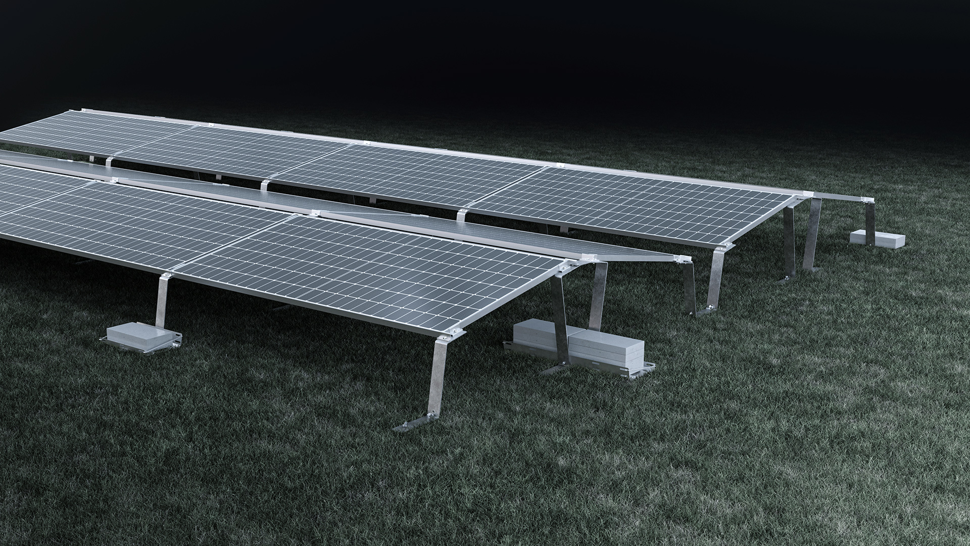
A driven profile isn’t always the most cost-effective solution: For difficult soil conditions, smaller projects, or special sites such as lined landfills,COMPACTGROUND GS is a viable option—our anchoring system that combines ground anchors, ballast trays, or both to secure the structure in place. This guide explains when to use which foundation system, how ground anchors and ballast work together, and how to choose between GS10 PLUS and GS15.
Every foundation serves the same purpose: it anchors the structure to the ground against wind and transfers the load into the subsoil. Since wind loads are not distributed evenly across an open area, the anchoring system does not need to be equally strong everywhere.
Have you already decided on a foundation type? Then set up the project directly inAEROTOOL. Wind and snow loads, local weather conditions, shading, and structural standards are all factored into the design.
COMPACTGROUND GS at a glance: two variants, 10° east/west or 15° south
COMPACTGROUND GS is a bracket system: Instead of deep-driven profiles, a row of shallowly founded brackets supports the module surface. The brackets are anchored to the ground with ground nails, weighted down with ballast trays, or secured with both; if necessary, each module can be nailed in place. Brackets, module clamps, ground anchors, and ballast trays form the core components; ballast securing devices, hammer drill adapters, and cable clips complement them depending on the project. The brackets and ground anchors are hot-dip galvanized, ensuring corrosion resistance. Two versions differ in their tilt and orientation:
Both have been tested in a wind tunnel and bear the CE mark.
All system components, data sheets, and assembly instructions → COMPACTGROUND GS product page
Pile Driving System orCOMPACTGROUND GS? When Piles Aren’t an Option—or Aren’t Worth It
On large, level areas with stable soil, a driven pile is generally the most cost-effective foundation solution.COMPACTGROUND GS is an option when a pile driving system is not suitable or cost-effective due to soil conditions, limited penetration depth on special sites, or the project’s scale. In such cases, the stabilization system—consisting of ground anchors, ballast trays, or both—is designed on a project-by-project basis.
On capped landfills, the surface seal must not be compromised by the construction, operation, or decommissioning of the PV system. Therefore, the permissible penetration depth is determined on a project-by-project basis in consultation with the relevant authorities and based on the site documentation. ForCOMPACTGROUND GS, 450-mm ground anchors and ballast trays are available for this purpose; the specific design determines how the two are combined.
Securing the System in Open Areas: Ground Anchors, Ballast, or a Combination—What Holds When
How the ground anchors are installed determines the installation process: You drive them in using a hammer drill. If an anchor encounters an obstacle, you unscrew it using the external thread and reinsert it at a different angle. An anchor can also be removed during dismantling.
Ground anchors are available in two lengths. The 450-mm-long ones are intended for landfills, where penetration depth is limited, and for use in combination with ballast trays. The 800-mm-long ones are designed for sites where frost heave must be prevented.
Ballast trays are available in lengths of 450 and 900 mm. The ballast retention bracket secures the stones in the tray and maintains load distribution where intended. The type of positional stabilization required at a given site depends on soil conditions and system design.
Ground anchors, ballast, or both: Because ground anchors and ballast trays can be freely combined, securing the pavers becomes a variable rather than a system requirement. WithCOMPACTGROUND GS, you place ground anchors and ballast trays where the calculations call for them and save on them where they aren’t needed—such as in the inner rows.
With our ground anchor pull-out test kit, you can determine the pull-out resistance of the intended anchoring system directly on-site. The result is incorporated into the project evaluation and helps determine the appropriate balance between anchoring and ballast.
Test kit and instructions → COMPACTGROUND GS download area
GS10 PLUS or GS15? Dense east-west layout or south-facing orientation with wider row spacing
Both versions are secured in the same way; they differ in tilt, orientation, and row spacing. The GS10 PLUS positions the modules at a 10° angle toward the east and west. Since there is no required shading angle, the rows can be arranged closely together. This supports high land utilization and a more consistent power output profile throughout the day.
GS15 orients the modules at a 15° angle toward the south. To achieve this, a shading angle of over 20° must be maintained, which correspondingly increases the row spacing. Whether an east-west or south orientation makes more sense for the site depends on the location, site layout, yield target, and project-specific load assumptions. InAEROTOOL, wind and snow loads as well as shading are factored into the design.
Why wind loads are not evenly distributed across an open-field site
An open-field system is exposed to the wind without any shielding, unlike a rooftop system, which benefits from the parapet and the building structure. You’re already familiar with this principle from flat-roof design: edge and corner zones bear higher loads than the interior area. In an open-field system, a second axis comes into play. The first row, facing the wind, is exposed to the oncoming airflow, while the rows behind it lie in its wake and are generally subjected to lower loads. The extent of this reduction depends, among other factors, on the tilt angle, row spacing, and wind direction. The zoning thus extends not only toward the edge but also in the direction of the airflow through the field.
An analysis of numerous wind tunnel tests on multi-row ground-mounted systems (Browne et al. 2020, see sources) describes a design method for such systems. The methodology is based on the North American ASCE 7 standard and does not replace project-specific design in accordance with the applicable standards for projects in Germany, Austria, and Switzerland.
For the foundation, this results in a simple principle: reinforce where the zone requires it, and save where it allows. This is precisely why ground anchors and ballast trays inthe COMPACTGROUND GS system can be freely distributed. The larger the field, the larger the internal area where this can be utilized; the project-specific design calculation determines how much can be saved.
Three steps to the right open-space substructure
- Measure the subsoil; don’t guess. Evaluate soil reports or test pits and determine the pull-out resistance using the test kit on-site.
- Determine the stabilization method. The ratio of anchoring to ballast is determined by the pull-out resistance and the wind load zone. If the nail holding force is sufficient, use anchors; if it is insufficient or the depth is limited, ballast trays compensate for the difference. Both can be configured differently for each zone; the distribution determines the project-specific design.
- Design the project in AEROTOOL. Using the information from the list below, you’ll receive a system design, a CAD plan, a project report, and a detailed bill of materials.
Record the following information for the design:
- Soil: Soil report or test pits, achievable installation depth, pull-out resistance per nail, and—for landfills—the approved penetration depth
- Location: Location, as well as wind load and snow load zones
- Area and layout: Area dimensions and layout, orientation (east/west or south), module data
The download section of the product page contains the documents for the next project steps: an intake form for GS10 PLUS and GS15, a GS10 PLUS leaflet with system data, assembly instructions for both variants, and the documentation for the ground anchor pull-out test kit.
Intake form, assembly instructions, and leaflet → COMPACTGROUND GS download section
Design your project now in AEROTOOL → Based on the specifications for the soil, location, and area, AEROTOOL generates a design and bill of materials tailored to your specific open space. The AEROTOOL Planning Guide shows you how a project is carried out there.
Still unsure whether a pile-driving system or COMPACTGROUND GS is right for your site? For project-related questions, you can reach us via the inquiry form on the COMPACTGROUND GS product page or at office@aerocompact.com.
Frequently Asked Questions About PV Mounting Systems for Open Spaces
When is a ground-anchor ballast system a better option than a pile-driving system?
When a pile-driving system isn’t suitable or isn’t cost-effective due to soil conditions, limited penetration depth, or project size. This applies, for example, to difficult subsoils, smaller projects, and special sites such as sealed landfills. If these conditions do not apply, a driven profile is generally the more cost-effective solution.
How does ground anchor installation work?
You install the ground nails using a hammer drill and an installation adapter (SDSMAX17). If a nail encounters an obstacle, you unscrew it using the external thread and reinstall it in a different location. A nail can also be removed during decommissioning.
Ground anchors or ballast—what determines the choice?
It depends on two factors: The pull-out resistance in the specific soil indicates how much holding force a ground anchor provides; the wind load zone indicates how much stability is required. If the anchoring is insufficient or the installation depth is limited, ballast trays supplement the stability. In many projects, it makes sense to use a combination that varies between perimeter and interior zones.
What are the two ground anchor lengths—450 mm and 800 mm—intended for?
The 450-mm ground nails are intended for landfills and for use in combination with ballast trays. The 800-mm ground anchors are used to prevent frost heave. The required length and any additional ballast needed at the site are determined by the soil report and the project-specific design.
What options are available—and how do I choose?
Two:COMPACTGROUND GS10 PLUS (10°, east/west, no shading angle required) andCOMPACTGROUND GS15 (15°, south, shading angle > 20°). The GS10 PLUS is suitable when a dense array and a more consistent power output profile are required. The GS15 is the south-facing variant with wider row spacing. Which design is suitable for the site depends on the location, site layout, and yield target; theAEROTOOL design takes wind and snow loads as well as shading into account.
Does every module row in the open-field installation bear the same wind load?
No. In multi-row ground-mounted systems, the wind load depends on the row’s position in the field: The first row facing the wind, as well as the edge and corner zones, are most exposed to the wind, while the inner rows are in the wake of the front rows and are generally subject to lower wind loads. The extent of this difference depends, among other factors, on the tilt angle, row spacing, and wind direction, and is determined by the project-specific design calculations. For planning purposes, this means that a uniform anchoring grid would have to be based on the highest load and would be oversized in areas where the design calculations indicate lower loads. A freely configurable mounting system consisting of ground anchors and ballast trays applies the holding force exactly where the design calculations require it—and reduces it where possible.
----------------------------------------------
Sources
- On the design method for wind loads on multi-row ground-mounted solar arrays:
M. T. L. Browne, Z. J. Taylor, S. Li, S. Gamble (2020): A wind load design method for ground-mounted multi-row solar arrays based on a compilation of wind tunnel experiments. Journal of Wind Engineering and Industrial Aerodynamics, Vol. 205, 104294. The method is based on wind tunnel tests conducted by RWDI using rigid pressure models; the paper describes a method using static and dynamic load factors that is compatible with ASCE 7 and addresses weaknesses in the ASCE 7 definition of “rigid structure” as well as in SEAOC PV2.
Note: The methodology is geared toward the North American design framework. For projects in Germany, Austria, and Switzerland, the applicable standards and national annexes are authoritative. AEROTOOL takes static standards into account in project planning.
Publication citation → DOI: 10.1016/j.jweia.2020.104294