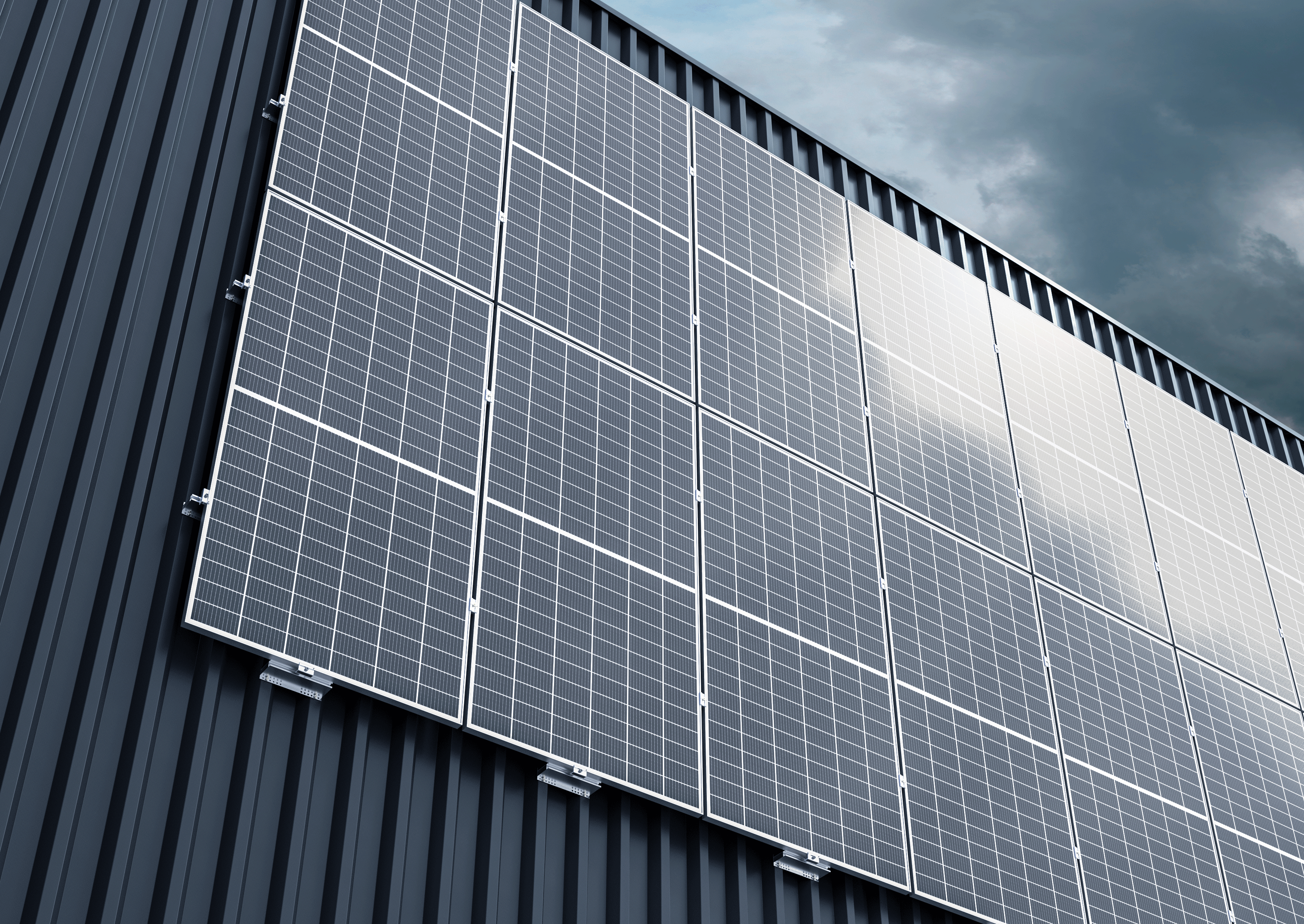
The substructure of a photovoltaic system installed on a facade follows different rules than one installed on a roof. A wall transfers loads through different pathways, is not subject to snow loads on the facade surface, and faces the sun vertically rather than at an angle. Therefore, the wall construction is the first critical factor: whether it’s concrete, trapezoidal sheet metal, or sandwich panels determines how forces are safely transferred to the load-bearing structure. This guide takes you from the wall construction to the appropriate substructure from ourCOMPACTWALL family and provides the values you need for design and quoting.
The choice of system comes down to one question: Where do wind, suction, and compressive forces act? For load-bearing concrete and trapezoidal facades, the wall structure itself absorbs these forces; in these cases, you installCOMPACTWALL TS/TL directly. An insulated sandwich panel, on the other hand, is an envelope structure, not a load-bearing element: WithCOMPACTWALL TR, the forces pass through the sandwich fasteners, bypassing the core, and into the wall studs behind it. These are two load paths and two system families, and each has its own verification chain in the structural analysis.
Do you already know your wall structure? Then determine the site-specific gust pressure (Qp)—that is, the wind pressure during gusts—directly inAEROTOOL → as the basis for the design.
Which wall construction? Three facade types, two system families
COMPACTWALL is a front-mounted system: Standard framed PV modules are installed parallel to the wall in front of the existing wall, while the facade itself remains unchanged. This distinguishes the solution from building-integrated PV, in which special modules replace the facade cladding. The frame height in the clamping range of 28 to 42 mm is decisive for module selection. Concrete and trapezoidal facades share one system family, while the sandwich facade has its own:
Both systems are CE-marked.
Concrete or trapezoidal facade? COMPACTWALL TS/TL mounts directly to concrete and trapezoidal sheet metal
On solid concrete and trapezoidal facades, you can installCOMPACTWALL TS/TL directly onto concrete or trapezoidal sheet metal. The system uses components from our provenCOMPACTMETAL family: the same rails, the same clamps, and the same thin-gauge sheet metal screws as those used on trapezoidal sheet metal roofs, as described in the guide to PV substructures for metal roofs. For wholesalers and installers, this means an additional application without the need to stock extra items—and on the job site, components that the installation team is already familiar with. In concrete, we use the CWS concrete screw 5 × 40 with an SW8 external hex: no anchors required, meaning one less step per mounting point. The lightweight construction keeps the additional load on the facade low, which is particularly important for existing buildings with limited structural reserves.
Four variants make up the product family, each available in two sizes and two wall spacings:
- TL — Portrait orientation, 18 mm wall spacing
- TLE — Portrait orientation, 80 mm wall spacing
- TS — Landscape orientation, 18 mm wall spacing
- TSE — landscape orientation, 80 mm wall clearance
TL and TLE are available in lengths of 250 mm (TL25/TLE25) and 380 mm (TL38/TLE38), while TS and TSE are available as short rails measuring 150 mm.
On trapezoidal sheet metal, the rib spacing also determines the rail length: TL25 covers 100 to 210 mm, while TL38 covers the range from 211 to 333 mm. For thin sheet metal, the TS15 short rail provides additional load-bearing capacity via three thin-sheet screws per mounting point.
The wall clearance is not a matter of preference. The 80 mm clearance of the raised variants creates a chimney effect: heated air rises along the vertical wall and draws heat away from the rear of the module—cooler cells operate more efficiently and age more slowly. This same gap accommodates a power optimizer, for which we offer a dedicated optimizer clamp. The raised components also make it easier to comply with fire safety regulations; you should clarify which requirements apply at the site on a project-by-project basis.
On the construction site, every step saved counts. The CLE20/CLM20 universal click clamp snaps into place instead of being screwed in and accommodates module frame heights from 28 to 42 mm; the end clamp measures 60 mm. Grounding pins are integrated into the clamp. In the raised TLE variants, the star-shaped punchout additionally provides equipotential bonding to trapezoidal sheet metal without requiring separate components. For other variants and substrates, the BJ8 grounding bridge and the WCL8-10 cable clamp are available for integration into the lightning protection system. The specific design is determined by the electrical engineering plan on a project-by-project basis.
All components, dimensions, and downloads: COMPACTWALL TS/TL — Product page with assembly instructions and planning guide →
Sandwich facade with PV? COMPACTWALL TR transfers the load to the wall stud, not into the core
A sandwich panel consists of two thin face sheets with an insulating core in between. It serves as both an envelope and insulation, but not as a load-bearing element for additional loads. This makes load transfer the primary challenge, and that is precisely why we have adapted ourCOMPACTMETAL-TR system—which has proven itself on sandwich roofs—for use on facades withCOMPACTWALL TR.
The exceptionally sturdy TR long rail concentrates the forces from wind, suction, and pressure. Two fasteners share the load: The sandwich self-tapping screw transfers wind loads directly into the load-bearing wall studs—whether made of wood or steel—via a patented load-transfer mechanism at the screw heads, while the thin-sheet metal screw absorbs the shear forces. The accompanying image shows a railing whose posts are not embedded in the cladding but in the supporting structure behind it.
The insulation core remains outside the load path, regardless of the spacing between the wall studs. The panel is not subjected to any additional load, and its warranty remains valid.
No snow load is generated on the vertical facade surface itself. Therefore, the design primarily considers dead weight as well as wind, suction, and compressive forces: The thin-sheet screws absorb the low dead weight, while the sandwich fasteners transfer the forces into the wall studs. The TR system also requires fewer penetration points—that is, fewer connections that must remain permanently watertight. We evaluate installation scenarios under roof surfaces, canopies, or extensions separately for potential snow accumulation.
Two rail heights are available for design purposes: TR59 and the 15 mm taller TR74, which is designed for high wind loads. The rail required for your project is determined by the site-specific load rating. If necessary, long rails can be integrated into the lightning protection system using the WCL8-10 cable clamp. With the TR series as well, the raised rail design ensures rear ventilation of the module’s backside.
Components, load transfer details, and the inquiry form for sandwich projects:COMPACTWALL TR — Product Page →
Yield on the facade: less annually, more during off-peak hours and in winter
A facade stands upright rather than at an angle, which shifts the yield throughout the day and year. When the sun is low—that is, early in the morning, late in the afternoon, and during the winter months—its flat rays strike a vertical wall oriented toward the sun at nearly a right angle, while they merely graze a gently sloped roof. In summer, the ratio is reversed.
Overall, this means that, according to calculations using the European Commission’s PVGIS 5.3, a vertical south-facing facade in Germany and Austria achieves approximately 70 to 72 percent of the annual yield of a well-oriented south-facing roof per unit of installed capacity. East- and west-facing facades yield less, but spread their generation across the morning and evening. Where a free, load-bearing roof is available, the roof is the first choice; the guides on flat roofs and pitched roofs describe the appropriate substructures.
A peer-reviewed measurement series from the University of York covering a full annual cycle demonstrates just how significant the advantage can be during off-peak hours: Vertically mounted bifacial modules delivered approximately 27 percent more power in the early morning and approximately 23 percent more in the late afternoon than tilted monofacial modules (Badran & Dhimish 2024). It is important to note the installation configuration: This involved a freestanding mounting system on light-colored gravel, not a wall-mounted system, and different cell technologies were compared. Therefore, the temporal generation profile—not the absolute value—can be applied to a facade.
This yields two rules of thumb for planning. If self-consumption is the priority and the load is concentrated in the morning and evening, east- and west-facing facades demonstrate their strengths. If the goal is to maximize the annual yield from the available wall area, a south-facing orientation is best: it generates the most power around noon and, relatively speaking, a significant amount in the winter. North-facing facades are generally not considered.
More critical than the orientation is shading on the facade: neighboring buildings, canopies, ramps, and extensions are positioned exactly where the yield is generated when the sun is low in the winter sky. A shading analysis covering the course of the day and the year should therefore be the first step in the planning process, not the last. We’ll work with you to evaluate the location, module type, and shading on a project-by-project basis.
Three steps to the right facade substructure
- Determine and document the wall construction —solid concrete or trapezoidal sheet metal calls forCOMPACTWALL TS/TL, while insulated sandwich panels call forCOMPACTWALL TR. To do this, note the following: for trapezoidal sheet metal, the rib spacing and sheet thickness; for sandwich panels, the material, the center-to-center distance of the wall studs, and the panel thickness; for concrete, the concrete grade and the condition of the surface. If there is an insulation layer or a cladding system in front of the load-bearing wall, clarify the load path with us in advance—this depends on the specific case.
- Determine the variant and orientation —portrait or landscape format depends on the module dimensions and wall grid. Regarding wall clearance: 18 mm is sufficient if no optimizers are installed and no larger rear ventilation gap is required; 80 mm is the recommended choice as soon as performance optimizers are installed or the module temperature needs to be reduced. On trapezoidal sheet metal, the rib spacing determines the rail length (TL25 for 100–210 mm, TL38 for 211–333 mm). ForCOMPACTWALL TR, choose between TR59 and the 15 mm taller TR74 based on the project-specific load assumptions.
- Design and Request a Quote — First, determine the site-specific Qp value inAEROTOOL; using this along with the module area and module weight, you can assess whether your site is suitable for a facade-mounted system. For systems under 50 kW, our planning guide will walk you through the configuration; for systems 50 kW and above, our technical planning team will assist you with the design. You can then determine the quantities per item using the assembly instructions and use this information to request a quote from us.
Determine the Qp value for your facade project inAEROTOOL → This provides the basis for the system design and quote.
Is the wall structure unclear, or is your project 50 kW or higher? Our technical planning team will assist you with the design.
All systems, data sheets, and downloads:PV mounting systems for facades at a glance →
Frequently Asked Questions About PV Mounting Systems on Facades
Which system is suitable for which facade?
By substrate:COMPACTWALL TS/TL for concrete and trapezoidal sheet metal facades,COMPACTWALL TR for sandwich facades. Both systems mount standard framed modules with a frame height of 28 to 42 mm in front of the existing wall. For other wall constructions—such as masonry with an external thermal insulation composite system (ETICS) or panel walls—we analyze the load path on a project-by-project basis.
Why does the sandwich facade need its own system?
Because a sandwich panel is designed as an envelope and insulation structure, not as a load-bearing element.COMPACTWALL TR therefore transfers wind, suction, and compressive forces via the TR longitudinal rail and sandwich fasteners past the insulation core into the wall studs behind it—whether the studs are made of wood or steel and regardless of their spacing. This places no additional load on the panel.
What is the difference between TL/TLE and TS/TSE?
The module orientation and the wall clearance. TL/TLE are installed in portrait orientation (rail lengths 250 and 380 mm), while TS/TSE are installed in landscape orientation (short rail 150 mm). The basic TL/TS variants sit close to the wall at 18 mm, while the raised TLE/TSE variants sit 80 mm away. You should opt for the 80-mm version if power optimizers are installed or if the module temperature needs to be reduced; check the fire safety requirements on a project-by-project basis.
When is a separate equipotential bonding required for facade PV systems?
This depends on the variant, the substrate, and the electrical design. For the raised TLE variants, the star-shaped perforations on the trapezoidal sheet metal provide equipotential bonding without the need for additional components. The CLE20/CLM20 snap-on clamps come with integrated grounding pins for this purpose. For all other variants and substrates, we offer the BJ8 grounding bridge (20 cm, stainless steel clamps with tinned copper wire) as well as the WCL8-10 cable clamp for integration into the lightning protection system. The specific design is determined by the electrical engineering plan on a project-by-project basis.
Does snow load on the facade play a role?
No snow load develops on the vertical facade surface itself—snow does not accumulate on a vertical module surface. Therefore, the design is primarily determined by the structure’s dead weight as well as wind, suction, and compressive forces. The installation situation must be evaluated: Where roof surfaces, canopies, or extensions extend over the system, sliding snow masses or roof avalanches may have an impact; in such cases, snow guards or an appropriate load factor must be included in the planning. The design is project-specific and follows the standards applicable at the site.
Is it even worth installing PV on a facade—since it’s at an unfavorable angle to the sun?
Yes, if you position it correctly. Per installed capacity, a vertical south-facing facade in Germany and Austria achieves about 70 to 72 percent of the annual yield of a well-oriented south-facing roof; east- and west-facing facades yield less. Where a free, load-bearing roof is available, the roof is the first choice. A facade becomes an attractive option in three cases: when the roof is occupied, shaded, or has reached its structural capacity; when solar installation requirements must be met and the roof area is insufficient; and when the consumption pattern is concentrated in the morning and evening—in which case an east- or west-facing facade increases the share of self-consumption, which replaces the full purchase price. Added to this is the proportionally higher winter contribution when the sun is low in the sky. A peer-reviewed measurement series by the University of York found that, during off-peak hours, vertically mounted bifacial modules generated approximately 27 percent (early morning) and approximately 23 percent (late afternoon) more power than tilted monofacial modules — on a freestanding mounting structure, not on a wall. What is transferable here is the generation profile, not the absolute value; location, orientation, shading, and module type must be evaluated on a project-by-project basis.
How do I plan the mounting structure, and when do I need the planning team?
First, useAEROTOOL to determine the site-specific gust pressure (Qp)—that is, the wind pressure during gusts—and use this, along with the module area and module weight, to assess whether your site is suitable for a facade-mounted system. For systems under 50 kW, the planning guide walks you through the configuration; for systems 50 kW and above, our technical planning team assists you with the design.
-----------
Sources and Data Basis
Regarding the yield profile of vertically mounted PV—general engineering context; no manufacturer specifications and no yield guarantee forCOMPACTWALL.
G. Badran, M. Dhimish (2024): Comprehensive study on the efficiency of vertical bifacial photovoltaic systems: a UK case study. Scientific Reports 14, 18380. Measurement series conducted by the University of York over a full annual cycle (February through December 2023). The study examined a freestanding vertical mounting system for bifacial HJT modules placed on light-colored gravel with a 50 cm row spacing, compared to a vertically mounted monofacial system and a tilted monofacial (polycrystalline, 45°) system. Results: Compared to the tilted monofacial system, output was approximately 27% higher in the early morning and approximately 23% higher in the late afternoon; compared to the vertically mounted monofacial system, the increases were 7.1% and 10.1%, respectively. The difference between the two comparisons shows that the majority of the advantage is attributable to the vertical orientation, with a smaller portion attributable to the bifacial design. Because the rear of the modules does not receive comparable ground reflection in a wall-mounted configuration, the temporal power generation profile can be applied to the facade, but not the absolute advantage.
Publication citation → DOI: 10.1038/s41598-024-68018-1
Regarding the order of magnitude of annual yield: Calculation using PVGIS 5.3 (European Commission, Joint Research Center) for Vienna, Munich, and Berlin, crystalline silicon modules, 14% system losses, south-facing orientation. A vertical facade achieves 69.9% (Vienna), 71.2% (Munich), and 72.1% (Berlin) of the annual yield of an optimally tilted south-facing roof (tilt of 39 to 40°). Other locations, module technologies, and shading conditions result in different values.