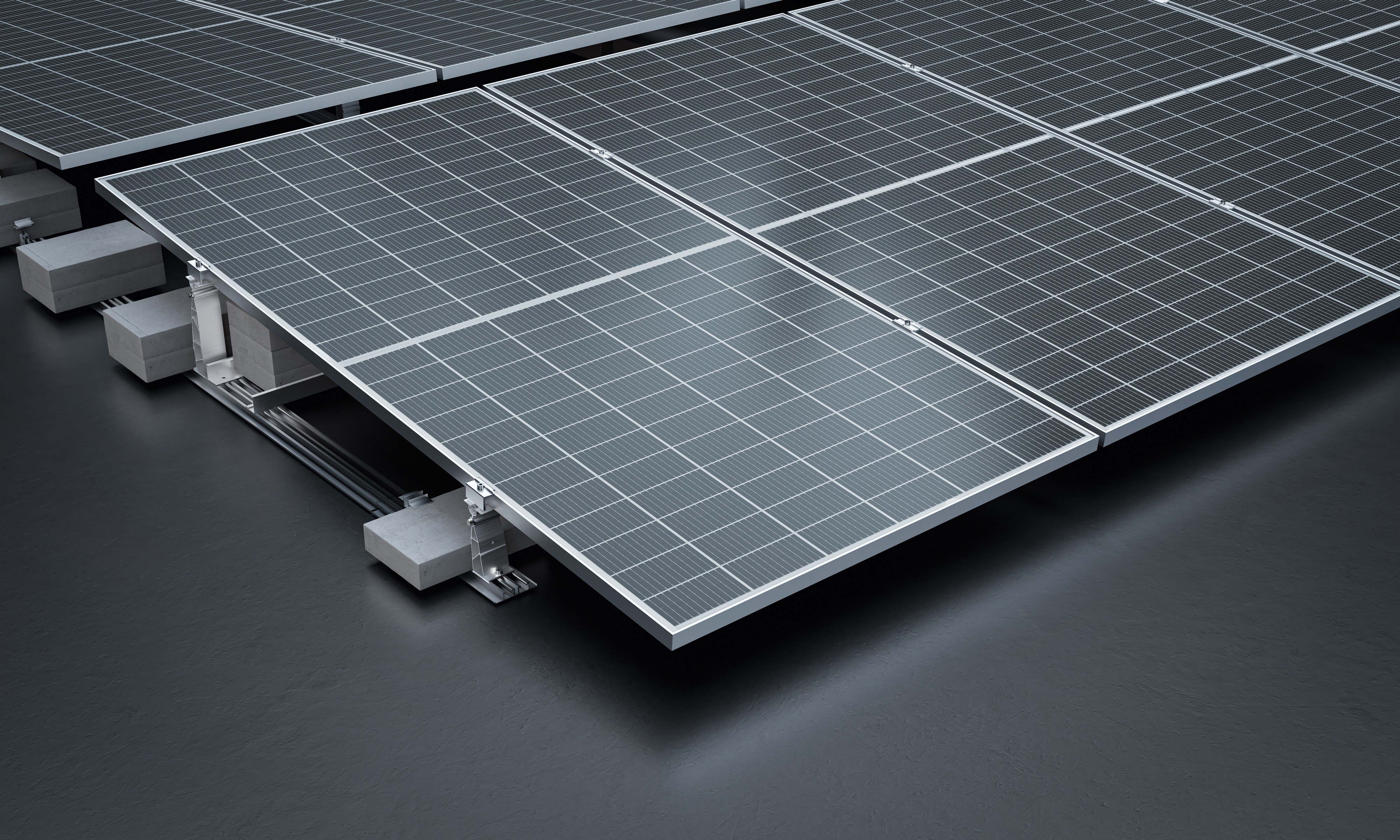
Other factors include the structural load reserve, module format, building and parapet height, as well as the wind and snow load zones at the installation site. This guide matches each roof situation with the appropriate system from ourCOMPACTFLAT family, explains how to secure the system against wind, and shows what information you need for the design. If there is a metal roof beneath the system, you’ll find the systems in the guide to PV substructures for metal roofs.
Essentially, all flat-roof systems solve the same problem: The roof is flat, the modules of a photovoltaic system require an incline, and any sloped surface creates suction in the wind. This leads to two separate requirements: The system must be secured against lifting and against shifting on the roof deck, and the effort required for this increases significantly toward the edges and corners of the roof. At the same time, the building must remain within its load-bearing capacity, and the roof waterproofing must retain its function. How a system meets these conditions determines your choice.
Do you already have the specifications for your roof? Then set up the project directly in AEROTOOL. You can trace the roof from the satellite image and receive a system recommendation, a ballast plan, and a project report that meets regulatory requirements.
A Comparison of Five Flat-Roof Mounting Systems:COMPACTFLAT S, S_BASE, SN 2, SN FAST, and GS
The table lists the application areas for each system and provides an initial guide; only the design analysis will show whether a system is suitable for your roof. Four factors influence your choice: module format, load data at the site, the time window available on-site, and whether the load is permitted to press against the insulation uniformly or at specific points.
What we’re basing our calculations on: All five COMPACTFLAT systems have been tested in a wind tunnel. The coefficients derived from these measurements, together with your project data, are incorporated into the structural analysis in accordance with the Eurocodes EN 1990, EN 1991-1-4 for wind, and EN 1991-1-3 for snow, along with the national annex applicable to your location. The structural analysis of the framework, coordination with the roof manufacturer regarding fasteners, and proper on-site installation must be clarified before placing an order.
COMPACTFLAT S: three fastening types and a free angle selection from 5° to 15°
COMPACTFLAT S is our bracket system for structurally demanding projects on non-green flat roofs. With 5°, 10°, or 15° south-facing orientation (S05/S10/S15), you can control the balance between peak yield, wind load, and ballast requirements: A flatter angle reduces suction and wind load, while a steeper angle increases midday yield. Protection against self-shading, on the other hand, is determined by the row spacing: The farther apart the module rows are, the lower the sun can be in the sky before one row shades the next. The east-west variant S10 PLUS delivers a more consistent yield curve throughout the day and keeps ballast requirements low, making it feasible even for roofs with limited load-bearing capacity.
Two details are important on the construction site: The PES protection pad is pre-installed and protects the roof membrane where the brackets rest. The universal click clamp also includes grounding pins for the electrical connection to the module frame. Documented projects demonstrate that the system is suitable for both small and large installations: 75 kWp in Italy, 485 kWp at the Käsekeller in Lingenau, and 2.2 MW in Čačak, Serbia.
COMPACTFLAT S: Data sheet, assembly instructions, and accessories →
COMPACTFLAT S_BASE: Base plate for point loads — for large modules and sensitive insulation
Large-format modules not only add more weight to the roof but also concentrate that weight on fewer support points. This is exactly whereCOMPACTFLAT S_BASE comes in: The patent-pending base plate distributes the load across a wide area rather than at specific points, while also accommodating ballast—or anchored connection points if the roof cannot support as much ballast. This makes the system suitable for use even on roofs with pressure-sensitive insulation.
On the construction site, you snap the east-west structure into place in landscape orientation with a 10° tilt and clamp the modules to the long side; the system already incorporates compensation for thermal expansion. Uneven roofs are not a disqualifying factor. Relevant for warehousing and logistics: All components are delivered compactly on pallets.
COMPACTFLAT S_BASE: Data sheet, assembly instructions, and palletization →
COMPACTFLAT SN 2: the modular rail system for high wind and snow loads
TheCOMPACTFLAT SN 2 modular system is designed for exposed locations with high wind and snow loads. It can be clamped either to the short or long side of the module frame and accommodates large-format modules up to 2,500 × 1,310 mm. Both orientations are possible—south and east-west at 5° or 10°—and two anchoring solutions are available for direct roof attachment. On soft insulation such as Durock (Rockwool), the 173-mm-wide base rail with pre-mounted protective mats can withstand snow loads of up to 3.6 kN/m² because it distributes the support forces over a larger area. Many components are pre-assembled at the factory, so only one person is needed on the roof.
COMPACTFLAT SN 2: all variants, anchoring solutions, and accessories →
COMPACTFLAT SN FAST: pre-assembled click-together installation for quick setup times
COMPACTFLAT SN FAST is based on the SN-2 system and is designed for speed: pre-assembled components, a screwless click-together system, and only three rail types per project. This not only shortens installation time but also reduces the risk of errors. This is a key advantage when working with different subcontractors. The system remains flexible nonetheless: clamping on both short and long sides is possible, and with short-side clamping, there are two row spacing options to choose from. The narrower spacing allows for maximum module density, while the wider spacing provides more room for maintenance work. The system is delivered entirely on Euro pallets, which simplifies storage and handling. Nearly all SN-2 accessories are compatible: cable management, load-distribution plates, anchoring options, and fall protection. We verify on a project-by-project basis whether a part is compatible with the selected variant.
Watch the COMPACTFLAT SN FAST installation video—plus data sheet and accessories list →
COMPACTFLAT GS: Elevated Mounting for Green Roofs and Bifacial Modules
On a green roof,COMPACTFLAT GS resolves a conflict of objectives: The PV system needs light, and so does the vegetation. The mounting system creates distance from the roof surface; the substrate structure correspondingly reduces the distance between plants and modules. The German Federal Association for Green Roofs (Bundesverband GebäudeGrün) recommends a minimum of 20 to 30 cm between the substrate surface and the bottom edge of the modules, depending on the choice of plants. The specific distance must be tailored to the planned vegetation so that plants beneath the modules receive light, water, and air, and the area remains accessible for care and maintenance.
There are three points you should clarify with the roofer early on in the green roof project: It must be determined to what extent the substrate can be counted as dead load; the waterproofing must be root-resistant to accommodate the vegetation; and, in addition, pathways of sufficient width are needed for care, maintenance, and fall protection. The project-specific design determines the substrate structure, ballast, and spacing.
This same high mounting height pays off with bifacial modules, which also generate electricity on the back side. The large distance from the roof surface allows reflected light to hit the back of the modules; how much light reaches them depends on the albedo of the underlying surface—the lighter the roof surface, the more light is reflected.
A one-year series of measurements on a white-painted industrial flat roof shows how significant this effect is in practice: At the start, the additional yield of bifacial modules compared to monofacial modules was around 17% on the east side and 14% on the west side. After twelve months, only 7% and 5% of that remained, respectively—soiling had reduced the albedo.*
For system design, this has two implications. Estimate the rear-side yield conservatively; do not use the initial value. And treat albedo as a maintenance parameter: A light-colored roof surface remains light-colored only if it is cleaned regularly—which requires that it be accessible. The high mounting height facilitates access to the roof surface. The GS is available in a south-facing orientation at 15° (GS15, without a wind deflector that would impede reflection) and in an east-west orientation at 10° (GS10 PLUS).
COMPACTFLAT GS: Leaflet, assembly instructions, and green roof details →
Ballasted, anchored, or hybrid: how do you secure the system against wind?
There are three concepts to choose from. They differ primarily in how much additional weight is placed on the roof and how it is distributed. The specific weight your roof requires is determined by the design. The roof membrane determines two things: whether a roof penetration is feasible and what coefficient of friction is used for the sliding analysis.
- Ballasted (without roof penetration): Block weights or gravel ballast secure the system without requiring a planned penetration of the waterproofing membrane. Two factors determine feasibility: the remaining load-bearing capacity of the roof structure and the long-term compressive strength of the insulation beneath the support points. To verify against slippage, you’ll also need the static friction coefficient between the support and the roof deck. This varies depending on whether the material is a membrane, bitumen, or gravel. You can find our measurement instructions for this in the download section.
- Mechanically anchored: Attachment points in the supporting structure absorb retaining forces and can reduce the ballast requirement. This is an important option when the load-bearing reserve is limited. Plan early for the proper integration of any penetrations through the waterproofing and coordinate with the roof manufacturer. Two roof anchor solutionsare available forCOMPACTFLAT SN 2 .
- Hybrid: Few attachment points, supplemented by ballast. This keeps the total weight below that of a purely ballasted solution without penetrating the entire roof surface. The distribution is determined by the project-specific design. In seismically active regions, this same combination serves a second purpose: The anchoring prevents the system from shifting due to seismic vibrations.
COMPACTFLAT S covers stone or gravel ballasting, anchor fastening, and the hybrid solution. The design is based on wind tunnel measurements and project-specific data; these allow the ballast to be tailored to the different roof zones. On buildings with limited load-bearing capacity, this can be the deciding factor in determining feasibility.
East-West or South: Which Offers More?
The compass direction determines two things at once: the shape of the yield curve and the load distribution on the roof. An east-west layout usually allows for more dense use of space; south-facing rows require spacing to prevent self-shading. However, the specific load distribution always depends on the geometry and design of the project.
- East-West (high space utilization, typically 10° tilt): The modules are arranged back-to-back like the two sides of a gable roof. This geometry reduces mutual shading and allows for a dense layout as well as power generation spread more evenly throughout the day. This is suitable for facilities whose load begins in the morning and continues into the evening. Systems:COMPACTFLAT S_BASE, SN FAST, S (S10 PLUS), and GS (GS10 PLUS). Plan for system-specific row spacing as well as aisles for maintenance and fall protection.
- South (5–15° tilt): A south-facing orientation can increase the specific yield per module and concentrates power generation more around midday. This is particularly beneficial if the roof area is larger than the planned system or if the center of gravity is at noon. In return, the rows require a calculated spacing to prevent self-shading, which reduces the installation density. You can adjust this by choosing the angle: S05 reduces wind load and ballast requirements, while S15 prioritizes yield per module. Systems:COMPACTFLAT S (S05/S10/S15), SN 2, and GS15.
Which orientation is most economical depends on four factors: location, available area, permissible roof load, and the facility’s load profile, which determines the proportion of self-consumption. AEROTOOL calculates shading, yield, and ballast requirements for the selected configuration. For the economic evaluation, you then compare these results with the operational load profile.
Three Steps to Finding the Right PV Mounting System
- Determine the roof membrane and module type. Green roof, bifacial, or conventional on concrete, bitumen, membrane, or gravel? The table above shows which systems are suitable. During the site visit, note the exact structure of the waterproofing immediately: It will later determine the coefficient of friction for the sliding analysis.
- Assess the framework conditions. Record everything in a single visit so that a second site visit isn’t necessary:
- Remaining load-bearing capacity according to the building’s structural analysis
- Long-term compressive strength of the insulation, which limits the allowable point load
- Building height, parapet height, and terrain category as input for wind load calculation
- Wind and snow load zone at the site
- Roof geometry, including edge and corner zones, roof structures, and skylights
- Dimensions and frame height of the planned modules
- If anchoring is planned: Coordination with the roof manufacturer
- Design the project in AEROTOOL. You import the data intoAEROTOOL and trace the roof directly from the satellite image; the stored wind and snow load maps as well as national standards are automatically incorporated. The result is a 3D system proposal, a structural analysis with a ballast plan, a project report compliant with regulatory requirements, a CAD drawing including DWG/DXF files, and a materials list.
Design your project in AEROTOOL now → Based on the information gathered during the site visit, AEROTOOL generates a system proposal, a ballast plan, and a project report compliant with regulatory requirements—all tailored specifically to your flat roof.
Still unsure about which system to choose? An overview of all flat-roof systems
Frequently Asked Questions About PV Mounting Systems on Flat Roofs
Which PV mounting system is suitable for a green roof?
COMPACTFLAT GS. We developed this high-riser system for green roofs and bifacial modules. It maintains a distance from the roof surface: the vegetation gets light, and the area remains accessible for care and maintenance. The German Federal Association for Green Roofs (Bundesverband GebäudeGrün) recommends a minimum of 20 to 30 cm between the substrate surface and the bottom edge of the module, depending on the choice of plants. The substrate can serve as ballast; whether and to what extent this is the case is determined by the project-specific design.
Does the system need to be ballasted or anchored?
Depending on the project, ballasting, anchoring, or a combination of both may be considered.COMPACTFLAT S accommodates all three options. Ballasting does not require any planned penetration of the roof membrane but adds extra weight to the roof; anchor points reduce the need for ballast but require professional integration into the waterproofing and coordination with the roof manufacturer. Four factors are decisive: roof structure, permissible roof load, compressive strength of the insulation, and wind exposure—the AEROTOOL calculates which securing method is suitable and how much ballast is required.
Which system is suitable for high snow and wind loads?
COMPACTFLAT SN 2. This rail-based modular system is designed for high wind and snow loads and can be clamped either to the short or long side of the module frame. It accommodates modules up to 2,500 × 1,310 mm. Whether your location qualifies depends on the snow load zone and elevation, as well as the wind zone and terrain category according to Eurocode with national annexes.
Which system is the fastest to install?
COMPACTFLAT SN FAST. Three factors combine to deliver this speed advantage: pre-assembled components, a screwless click-together system, and only three rail types per project—fewer different parts mean less sorting and fewer mistakes. The system is delivered on Euro pallets, which simplifies storage and transport on the construction site. If you need a south-facing orientation, SN 2 is the alternative: it also features pre-assembled components and can be installed by a single person.
Are bifacial modules worth it on a flat roof?
That depends on the albedo of your roof surface. On light-colored or light-coated roofs, the combination of bifacial modules and the high mounting height ofCOMPACTFLAT GS is worthwhile — a one-year measurement series on a white-painted industrial flat roof initially showed an additional yield of about 17% for east-facing modules and 14% for west-facing modules. After one year of operation, these figures had dropped to 7% and 5%, respectively, because soiling had reduced the albedo.* On dark roof surfaces, the yield from the rear side is correspondingly lower. Therefore, use conservative estimates and factor in roof cleaning when planning.
What is the optimal tilt angle for a flat roof?
WithCOMPACTFLAT, you can choose between 5°, 10°, and 15°. The relationship is always the same: A steeper angle can increase the yield per module, but it also increases wind load, ballast requirements, and the necessary row spacing to prevent self-shading. As a result, the system produces fewer kilowatts-peak per unit area. 10° is often a good compromise; 15° is suitable when there is sufficient space and load-bearing capacity; and the 5° S05 variant is designed for roofs where low wind load and minimal ballast are the primary considerations. The appropriate angle is determined by the project-specific design.
How much additional load does a flat-roof substructure place on the roof?
Without project data, it is not possible to provide a reliable flat rate per square meter. Furthermore, ballasted systems do not distribute the additional load evenly: In edge and corner zones, more ballast may be required than in the center of the roof due to stronger wind suction. Anchor fasteners and hybrid solutions can reduce the total weight, but they require properly installed connection points. In addition to the total load, the design evaluates a second limit that is often reached first: the allowable point load on the insulation beneath the support points.AEROTOOL provides the project-specific value, including a ballast plan.
----------------------------
Sources
* Regarding the data basis for bifacial yield: The values cited are derived from a one-year series of measurements on a white-painted industrial flat roof. They apply to this specific installation and are not transferable to other roof surfaces.
W. Mühleisen et al. (2020): Operation and Evaluation of a Bifacial PV Module Test Setup. EU PVSEC Conference Proceedings, 37th EU PVSEC, September 2020.
Publication Citation → Silicon Austria Labs
Bundesverband GebäudeGrün e. V. (BuGG): Technical Guide for the Planning and Construction of PV-Green Roof Combinations. 2025.
Publication reference → Bundesverband GebäudeGrün